To tylko jedna z 161 stron tej notatki. Zaloguj się aby zobaczyć ten dokument.
Zobacz
całą notatkę
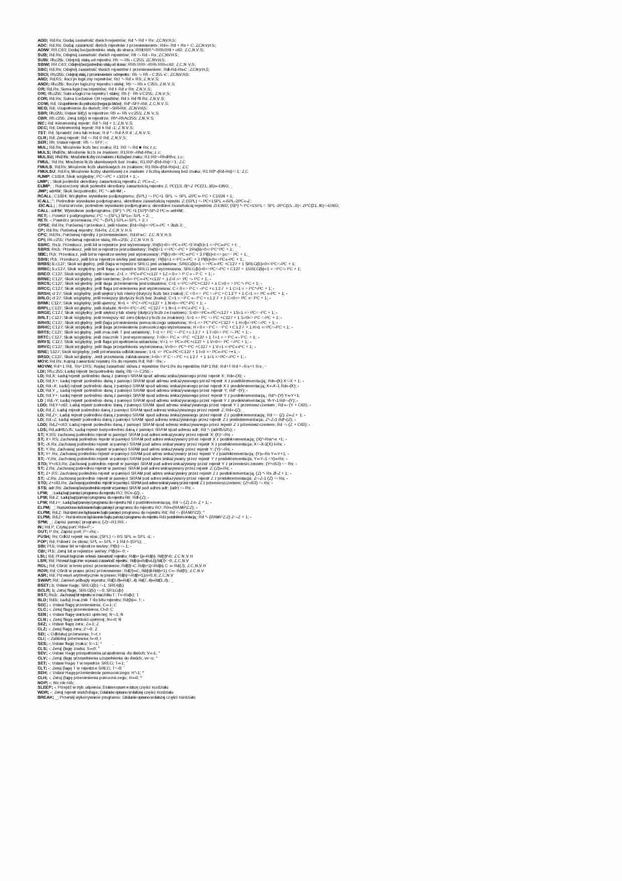


Instruction Set Nomenclature
Status Register (SREG)
SREG:
Status Register
C:
Carry Flag
Z:
Zero Flag
N:
Negative Flag
V:
Two’s complement overflow indicator
S:
N ⊕ V, For signed tests
H:
Half Carry Flag
T:
Transfer bit used by BLD and BST instructions
I:
Global Interrupt Enable/Disable Flag
8-bit
Instruction Set
Registers and Operands
Rd:
Destination (and source) register in the Register File
Rr:
Source register in the Register File
R:
Result after instruction is executed
K:
Constant data
k:
Constant address
b:
Bit in the Register File or I/O Register (3-bit)
s:
Bit in the Status Register (3-bit)
X,Y,Z:
Indirect Address Register
(X=R27:R26, Y=R29:R28 and Z=R31:R30)
A:
I/O location address
q:
Displacement for direct addressing (6-bit)
Rev. 0856I–AVR–07/10
I/O Registers
RAMPX, RAMPY, RAMPZ
Registers concatenated with the X-, Y-, and Z-registers enabling indirect addressing of the whole data space on MCUs with
more than 64K bytes data space, and constant data fetch on MCUs with more than 64K bytes program space.
RAMPD
Register concatenated with the Z-register enabling direct addressing of the whole data space on MCUs with more than 64K
bytes data space.
EIND
Register concatenated with the Z-register enabling indirect jump and call to the whole program space on MCUs with more
than 64K words (128K bytes) program space.
Stack
STACK: Stack for return address and pushed registers
SP:
Stack Pointer to STACK
Flags
⇔:
Flag affected by instruction
0:
Flag cleared by instruction
1:
Flag set by instruction
-:
Flag not affected by instruction
2
AVR Instruction Set
0856I–AVR–07/10
AVR Instruction Set
The Program and Data Addressing Modes
The AVR Enhanced RISC microcontroller supports powerful and efficient addressing modes for access to the Program
memory (Flash) and Data memory (SRAM, Register file, I/O Memory, and Extended I/O Memory). This section describes
the various addressing modes supported by the AVR architecture. In the following figures, OP means the operation code
part of the instruction word. To simplify, not all figures show the exact location of the addressing bits. To generalize, the
abstract terms RAMEND and FLASHEND have been used to represent the highest location in data and program space,
respectively.
Note:
Not all addressing modes are present in all devices. Refer to the device spesific instruction summary.
Register Direct, Single Register Rd
Figure 1. Direct Single Register Addressing
The operand is contained in register d (Rd).
Register Direct, Two Registers Rd and Rr
Figure 2. Direct Register Addressing, Two Registers
Operands are contained in register r (Rr) and d (Rd). The result is stored in register d (Rd).
3
0856I–AVR–07/10
I/O Direct
Figure 3. I/O Direct Addressing
Operand address is contained in 6 bits of the instruction word. n is the destination or source register address.
Note:
Some complex AVR Microcontrollers have more peripheral units than can be supported
... zobacz całą notatkę
Komentarze użytkowników (0)